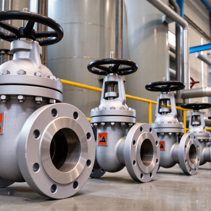
| Solid-wedge gate valve | A single-piece wedge moves between the seats. Available with rising-stem or non-rising-stem arrangements. | General isolation in water, oil, gas, and utility piping where flow is normally fully open or fully closed. | API 600 for applicable bolted-bonnet steel gate valves; ASME B16.34 for pressure-temperature ratings and valve construction; ASME B16.5 or B16.25 for applicable end connections. | Confirm pressure-shell and closure testing requirements against the purchase specification and the applicable edition of API 598 or ISO 5208. Check material records, dimensions, and marking. | Install with the flow direction and orientation allowed by the manufacturer. Provide sufficient clearance for handwheel travel and stem movement; avoid using the valve to regulate flow. | Inspect packing and external joints for leakage. Operate periodically where service conditions allow; investigate rising operating torque before forcing the handwheel. |
| Flexible-wedge gate valve | A one-piece wedge with a circumferential groove or other flexible feature can accommodate limited seat or body deflection. | Process and utility services where thermal changes or piping loads may cause small alignment variations. | Verify the applicable design standard, pressure class, materials, and end dimensions in the project specification; API 600 and ASME B16.34 are commonly referenced for relevant steel valves. | Check shell and seat leakage acceptance criteria, test medium, duration, and any supplementary examination specified by the purchaser. | Support and align adjoining pipework so the valve body is not subjected to excessive loads. Follow the manufacturer’s instructions for stem position and actuator access. | Monitor for leakage, abnormal torque, and packing wear. Maintenance intervals depend on service conditions and operating frequency. |
| Parallel-slide gate valve | Uses parallel seating surfaces and sliding gate elements; specific designs may use springs or pressure-assisted seating features. | Selected steam, power, and process services when the valve design is specifically qualified for the operating conditions. | Confirm that the selected design is covered by the specified valve standard and is suitable for the service. Verify pressure-temperature limits and material compatibility. | Specify closure test method and acceptance criteria appropriate to the design. Review manufacturer test records and required inspection documentation. | Observe any required flow direction, installation position, and warm-up or operating procedure stated by the manufacturer or system designer. | Check for stem packing leakage and smooth travel. Do not assume that maintenance procedures for wedge-gate designs apply to parallel-slide designs. |
| Pressure-seal bonnet gate valve | Uses internal pressure to energize a bonnet sealing arrangement; commonly selected in particular high-pressure and high-temperature designs. | Some power-generation and process applications where pressure, temperature, and operating conditions match the valve’s qualified design. | Verify design-standard scope, pressure-temperature rating, materials, and applicable piping code. Pressure-seal construction is a bonnet design feature, not a substitute for checking the complete valve specification. | Review pressure-boundary test records and the specified closure test. Confirm that inspection and test requirements match the project code and service. | Follow the manufacturer’s installation and tightening procedures. Allow access for inspection and any design-specific bonnet maintenance. | Inspect external sealing areas and stem packing. Any pressure-seal maintenance should be performed using the manufacturer’s procedure and appropriate safety controls. |
| Rising-stem (OS&Y) arrangement | The stem rises or lowers as the valve is operated; the stem position provides a visible indication of travel. OS&Y describes the outside-screw-and-yoke arrangement. | Locations where visible valve position and accessible stem maintenance are useful, subject to space and environmental conditions. | Check the applicable valve design standard, actuator or handwheel requirements, and stem and yoke details in the approved datasheet. | Inspect stem movement, packing, travel limits, and closure performance as part of the specified inspection and test plan. | Provide overhead clearance for the rising stem and handwheel. Protect exposed stem threads from impact, dirt, and corrosion. | Keep exposed threads clean and appropriately lubricated where instructed. Inspect packing and verify full travel without forcing the valve. |
| Non-rising-stem (NRS) arrangement | The stem rotates without moving axially outside the valve; the gate moves internally. Stem rotation alone may not show the exact gate position. | Installations with limited vertical clearance, including some buried or compact piping arrangements when the valve is designed for that service. | Verify suitability for the installation, stem sealing arrangement, pressure rating, materials, and any applicable product standard. | Check operation and closure performance using the specified test procedure. For buried service, confirm any required coating and inspection requirements. | Ensure operating-nut or actuator access and use the specified operating key or extension. Follow the manufacturer’s orientation and burial instructions. | Inspect operating components and stem seals where accessible. Buried valves may require planned access provisions for operation and inspection. |
| Cast-steel body material selection | Common cast carbon-steel grades include ASTM A216 WCB and WCC; alloy or stainless cast grades may be specified for other service requirements. | Selection depends on design temperature, pressure, corrosion allowance, fluid compatibility, and applicable piping code. | Confirm the exact material specification and grade, heat treatment, pressure-temperature rating, and any supplementary requirements on the approved datasheet. | Review material test reports, heat and grade traceability, and specified nondestructive examination. Additional examination depends on the code, design, and purchase order. | Match valve materials and end connections to the piping system. Consider galvanic compatibility, insulation, and external corrosion protection where relevant. | Monitor corrosion, coating condition, and leakage. Select inspection methods and intervals based on the service risk and applicable integrity program. |