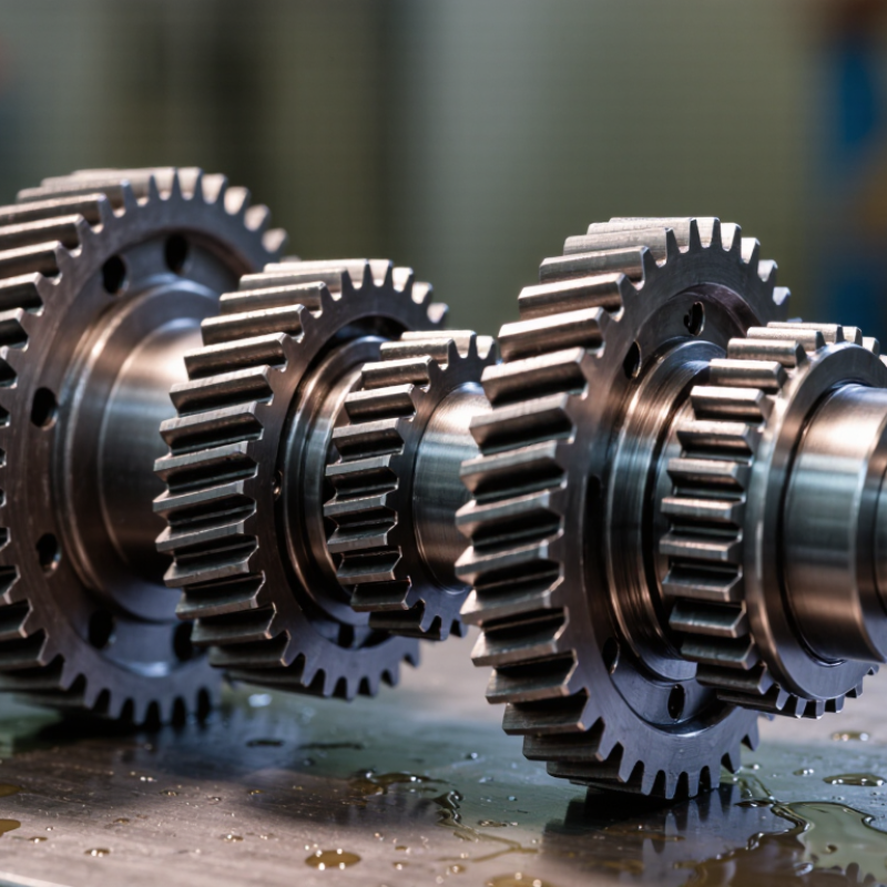
| 1 | Material Quality | Confirm the gear steel grade, cleanliness, heat-treatment condition, and traceability. Common gear materials include case-hardening steels for a hard wear-resistant surface and tough core. | The material should match the required torque, shock loading, speed, and operating temperature. Surface hardness and core hardness should be specified for the intended application rather than selected by appearance alone. | Material certificate, heat-treatment report, hardness test results, and batch or heat number traceability. | Correct material selection helps prevent tooth pitting, bending fatigue, cracking, and premature wear. |
| 2 | Heat Treatment | Review carburizing, induction hardening, nitriding, or through-hardening details, including case depth, hardness profile, distortion control, and post-treatment finishing. | For case-hardened gears, effective case depth is normally defined according to load and tooth size. The supplier should provide the specified measurement method and acceptance limits. | Heat-treatment process record, hardness map, case-depth test, and distortion inspection report. | A suitable hard surface improves wear and contact-fatigue resistance while a tougher core supports shock loads. |
| 3 | Manufacturing Precision | Check tooth profile, lead accuracy, pitch variation, runout, concentricity, bore dimensions, and keyway or spline accuracy. | Require a clearly stated gear accuracy grade under a recognized system such as ISO 1328 or AGMA 2015. The required grade depends on speed, noise limits, load, and transmission accuracy. | Coordinate-measuring-machine report, gear inspection chart, dimensional inspection report, and drawing with tolerances. | Higher precision improves load distribution, reduces vibration, and lowers the risk of uneven tooth contact. |
| 4 | Load and Rating Capacity | Compare the cluster gear’s transmitted torque, rotational speed, duty cycle, shock factor, and contact pattern with the actual operating conditions. | Request rating calculations based on recognized methods such as ISO 6336 or AGMA 2101. Check both tooth-root bending strength and flank contact strength. | Gear-rating calculation, maximum allowable torque and speed, service-factor assumptions, and application load profile. | A gear that fits dimensionally may still fail if its bending or contact-fatigue capacity is inadequate. |
| 5 | Surface Finish and Tooth Geometry | Inspect tooth flanks for grinding burns, scoring, dents, sharp edges, burrs, and irregular contact marks. Verify module or diametral pitch, pressure angle, helix angle, face width, and backlash. | Surface-finish and backlash limits should follow the engineering drawing and operating requirements. Excessive backlash can cause noise and impact loading; insufficient backlash can cause overheating or seizure. | Final inspection report, surface-roughness readings, backlash measurement, and tooth-contact inspection. | Accurate geometry and suitable finish support smooth meshing, efficient power transfer, and stable lubrication. |
| 6 | Durability and Reliability | Evaluate expected service life, lubrication conditions, contamination exposure, temperature range, corrosion risk, and resistance to repeated starts or shock loads. | Use the calculated duty cycle and service factor instead of relying only on a nominal load rating. Confirm compatibility with the specified lubricant and maintenance interval. | Endurance or validation-test data, failure-mode analysis, recommended lubricant, maintenance requirements, and warranty terms. | Durability depends on the complete operating system, including alignment, lubrication, temperature, and maintenance—not only on gear material. |
| 7 | Fit, Compatibility, and Quality Control | Verify center distance, shaft or bore dimensions, spline or keyway form, gear orientation, axial location, mating-gear geometry, and installation clearances. | All interface dimensions should be checked against the approved drawing. A first-article inspection and sample trial assembly are recommended for critical applications. | Approved drawing, first-article inspection report, calibration records, process-control plan, and trial-assembly results. | Correct fit prevents misalignment, excessive noise, concentrated tooth loading, installation damage, and costly downtime. |